|
|
| |
TERMINALS |
| |
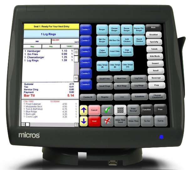
Micros WS6 |
| |
Performing a Factory Reset from BIOS
To perform system recovery from the BIOS:
- Enter the BIOS.
- Connect a USB keyboard to the Workstation 6.
- Power on or restart the workstation.
- Press F2 immediately after pressing the power button and
before the BIOS splash screen. You can press F2 repeatedly until the
Configuration Utility starts. If the workstation boots into the
operating system without starting the utility, restart the
workstation and try again.
- On the Advanced tab, use the arrow keys to select Special
Configuration, and then press Enter.
- Select Factory Recovery, and then press Enter.
- Select Enabled, and then press Enter.
- Press F10, select Yes, and then press Enter to save the
configuration changes and exit the configuration utility. The
Workstation 6 automatically restarts.
- On the Choose an Option screen, click Troubleshoot.
For the 610:
On the Troubleshoot screen, click Reset your PC, and then click
Next.
Click Fully clean the drive, and then click Reset to
finish restoring factory settings.
For the 620 and 650:
On the Troubleshoot screen, click Factory Reset.
Select Y to reset the Windows partition to factory default.
When the restoration is complete and the workstation restarts, you can
begin the operating system setup. |
| |
Micros WS5 |
Operational Troubleshooting |
• Operational Troubleshooting
This section provides a detailed description of the Workstation 5A boot
sequence for both the Windows Embedded CE and POSReady 2009 operating
systems. To aid in troubleshooting, background information is provided
for multiple boot configurations, pre-boot firmware applications,
platform updates, and the Client Application Loader.
• Checking the Power Supply and System Board Voltages
This section establishes the Standby and Working domain voltages, then
goes on to show how to check these voltages on a unit that will not
power-up.
• Workstation Recovery and Platform Update Procedures
The methods available for restoring a Windows Embedded CE 6.0 or
POSReady 2009 Workstation 5A are discussed in detail.
• LCD Display Related
This section lists all display and display quality problems. In
addition, jumper settings for the supported LCD panels are provided.
• Touchscreen Related
This section provides information on touchscreen related issues
including calibration.
• Local Area Network
This section provides network related issues, how to interpret the LEDs
in the Ethernet connector, etc.
• Peripheral Related
This section covers the WS5AA POS interfaces including COM Ports, IDN,
and Magnetic Stripe Reader.
• Diagnostic Overview
This section covers the built-in diagnostic utilities provided with the
Windows Embedded CE 6.0 and POSReady 2009 operating system
configurations. For Windows Embedded CE 6.0 configurations, a
description of each platform file is provided. |
| TERMINAL OPERATING SYSTEMS |
TERMINAL OPERATING SYSTEMS
Microsoft Operating System Support
The MICROS PCWS 2015 is offered with Microsoft Windows 7 Pro
preinstalled on a single 160G SATA II hard drive. Microsoft Windows
Embedded POSReady 2009 (POSReady 2009) is also available for
applications that can support this operating system.
It should be noted that both Microsoft POSReady 2009 and Microsoft
Windows 7 require the use of anti-malware (anti-virus) software to meet
PCI-DSS requirements. Also, end users must provide a mechanism to
receive regular operating system updates from Microsoft to ensure they
remain up to date with any security related corrections.
Microsoft POSReady 2009
POSReady 2009 replaces Microsoft Windows Embedded for Point of
Service (WEPOS) as Microsoft's operating system targeted for POS
devices. POSReady 2009 is a prepackaged version of Windows XP embedded,
the componentized version of Windows XP. By tailoring this operating
system for the specific needs of POS, Microsoft is able to reduce the
overall size of the operating system and offer it at a lower cost.
POSReady 2009 improves on WEPOS in a number of areas, including the
ability to install and remove OS components and applications at will,
addition of the most current Microsoft technologies such as .NET
framework 3.5, Silverlight and SQL Server Express, and seamless
connectivity using the latest POS peripheral drivers.
Microsoft Windows 7 Professional
Windows 7 Professional is Microsoft’s full desktop operating system,
providing capabilities beyond that found in the POSReady 2009 embedded
operating system.
As part of MICROS licensing agreement with Microsoft, the Windows 7
Certificate of Authenticity applied to the MICROS PCWS 2015 allows users
to downgrade the Windows 7 operating system to Microsoft Windows XP
Professional if desired. This capability allows users to purchase the
MICROS PCWS 2015 with Windows 7, downgrade to Windows XP and use it with
applications that may not be ready to support the newer operating
system. When the user is ready, they can restore the original Windows 7
operating system.
|
| |
How to Add a Terminal To check how many
licenses you have, open the License Manager. The quickest way is to open
the run manager (Windows Key + R) and type licmanager. You can
also find it through the start menu: Start -> All Programs | MICROS
Applications | Utilities | License Manager.
Once you open this, go to the POS 3700 tab. On the right hand side, you
will have the list of license codes, and above that you will have three
additional tabs. Click the Clients tab. While you might have more
license codes than are listed, most Mcros installers put them all in.
Check how many you have listed and compare to how many workstations you
have in use... if they are all in use, you will need another code. If
they aren't all in use, you can add either a CE or Win32 client without
needing another code. Even if they are all in use, it is possible that
you have an additional license code, but you'll need someone who has
access to the Micros website to check for you. You'll have to give them
your key number for that.
How to configure the system for another workstation.
1) Open POS Configurator and go to the Devices tab.
2) Click on Network Node
You'll find a list of all of your workstation, all of your network
printers, your server, and any KDS you might have. This is where you
define the device type (Win32, Workstation4, mTablet, etc) as well as
the networking settings.
a) Click on the last workstation in your list, in this case UWS5. You
only have four workstations, but you have five configured. This is
pretty convenient. Verify that an IP Address and Subnet Mask are
configured for UWS5. Once you have verified that, in the Workstation
Type dropdown, change it to Workstation, probably from Workstation4.
Workstation is what Micros calls the Win32 workstation type while
Workstation4 is the WinCE type.
b) Click the green check box to save the change you made, and click the
Update Host File button
3) Close that window, and now click on Devices.
This list pairs a network node with a device name; for workstations
there really isn't anything to do here. If the UWS5 doesn't exist in
this list, click the blue + button to add a new record. We only have to
deal with the first tab: Set Device Type to User Workstation and Network
Node to UWS5.
4) Close this window, and now click on User Workstations
This is where most of the actual configuration for the workstation takes
place. Hopefully this also has a fifth workstation configured already.
If not, click on UWS4, and click the blue + button.
a) In the device name column, click and a dropdown will open. Select
UWS5.
The rest is a bit more tricky; you're going to have to jump back and
forth between UWS5 and UWS4 so that you can mirror the settings for all
the tabs.
Once you've done all of that (and hopefully you won't have to because
you have a UWS5 already setup), you can install the actual CAL software
on the computer. It has to be on the same network as the rest of the
Micros computers.
|
| |
How to do a Windows CE 6 Factory Reset on WS 5/5A
The procedure to initiate a Factory Restore can be found below and
applies to Windows Embedded CE 6.0 unit only
WARNING: Factory Restore deletes all files from the
Compact Flash Card.
If required, take steps to preserve files on the CF card before
running Factory Restore. If the CF Card is formatted to FAT32
(partition type 0x0b), it will not be erased and may cause Factory
Restore to fail
1. Connect a USB Keyboard to the workstation and power-up.
Be sure to remove any USB Flash or Thumb Drives attached to the IO panel
USB ports.
2. The instant the BIOS splash screen appears, press the key
combination [ALT-M]. Note: Some keyboards may not initialize in
time to detect this key combination.
As an alternative, you can press [Del] to enter BIOS Setup,
select the Features Configuration screen, and set the
WIN_CE_FACTORY_RESTORE field to 'Enabled'.
Press OK to continue. The screen prompts for the system password.
3. If you have not changed the default system password,
enter 'Grnbelt' (case sensitive) and press Enter. Press 'Y' to
confirm
If the password entry is successful, the screen returns to the Setup
Main Menu.
4. Select 'Write to CMOS and Exit' and press Enter. Press 'Y'
to confirm. The unit restarts and prompts 'Factory Restore in Progress -
Please Wait.'
5. When the process is complete, the unit automatically restarts.
Connect the workstation to properly configured CAL server to receive the
latest platform files and BIOS
|
| |
Calibrating The WS5/5A Touchscreen
Calibrating the touchscreen is the process of aligning the touchscreen
glass with the underlying video display.
When to Calibrate the Touchscreen
• If the LCD panel or touchscreen glass have been replaced or
when installing a new workstation.
• Any time the cursor does not follow the movement of your finger,
or does not reach the edges of the touchscreen.
• After performing a workstation Personality Swap (Windows CE Only).
Tips for Calibrating the Touchscreen
• Perform the calibration procedure in the position (sitting or
standing) that the workstation is normally used.
• Face the Touchscreen directly. If the workstation is on a stand,
adjust it to the optimum viewing angle.
Windows Embedded CE 6.0
1. From the desktop, press Start -> Settings -> Control Panel and
tap the ‘EloTouch icon. Touch or click the ‘Calibrate’ button to
proceed.
• If you do not touch the screen within twenty seconds, the
calibration utility will shut down and retain the previous
calibration values.
2. To begin, touch the center of the cross-hair that appear on the
screen. Continue to touch each target at the positions indicated -
upper right, and lower right.
• Make sure the cursor follows you finger at each corner of the
screen.
Press [Accept] to compete the procedure and exit the
utility.
POSReady 2009
Touch the desktop icon to start the touchscreen calibration.
|
| |
Checking the WS5 Power Supply and System
Board Voltages
Before checking the power supply and system board
voltages, see Chapter 2 for more information about the Standby and
Working power domains as implemented on the WS5 System Board,
ABRD88.
The Standby voltages are ‘always on’ - when the unit
is connected to AC Power.
Refer to Figure 3-4 and the procedure on the next
page to check the Standby voltages in the proper sequence.
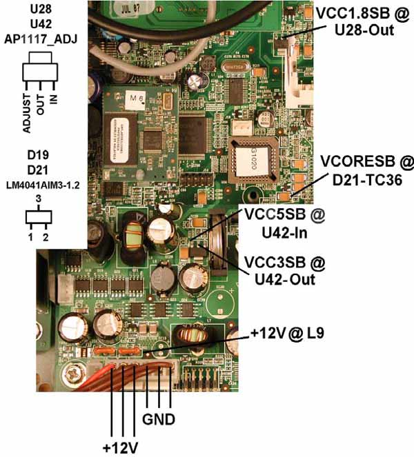
Checking the WS5 System Board - Standby Voltages
SHOCK HAZARD
Hazardous AC
and DC voltages are present on the power supply heat sinks when the
AC Power cable is connected to an AC source.
Checking the Power Supply and System Board Voltages
1. Start with the +12V output from the power supply at J16.
- If +12V is not available, remove the AC Power Cable
and check the power supply fuse located near the AC input
connector.
- If the fuse is OK, but the power supply produces no output,
check the AC input cabling through the AC input connector
mounted to the chassis.
- If +12V is not available, replace the Power Supply.
2. If +12V is available, check VCC5SB at the (IN)put pin of
adjustable regulator U42. VCC5SB is generated by regulator #1 in
U38. This regulator is configured to run as long as +12V is
available.
3. If VCC5SB is available, check VCC3SB at the (OUT)put pin of
adjustable regulator U42.
4. If VCC5SB is available, check VCORESB at the junction of D21 and
TC36. VCORESB powers the LX800 Processor and TFT Controller.
5. If VCC3SB is available, check VCC1.8SB at U28-Out. If the Standby
voltages are present, but the board will not start when you press
the power button, see the next section.
WS5 System Board - Working Voltages
On a unit where the Standby voltages are present, but fails to respond
to the power button, the Working domain voltages can be checked as
outlined in Figure below and the following text.
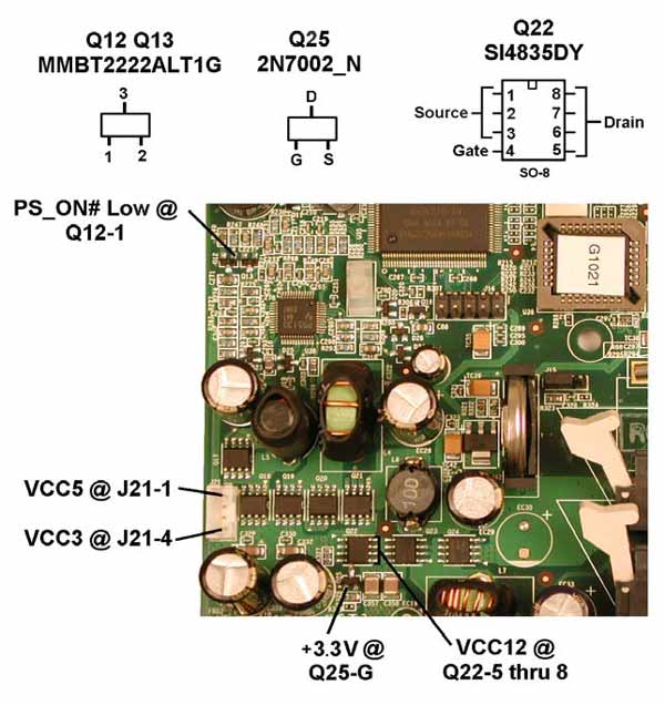
Checking the WS5 System Board Working Voltages, 2
The working voltages depend on the standby voltages. Before proceeding,
make sure all standby voltages shown in the figure above are available. With
AC power connected, press the power button and check the following:
1.Start with PS_ON# at the base of Q12 or Q13. It should be low.
- Q12 and Q13 enable the VCC3 and VCC5 regulators, part of
U38.
- PS_ON# is derived from the WORKING output of the Companion
Device. Q16 inverts WORKING to active-low PS_ON# (Sht. 8).
2. Check the VCC3 and VCC5 outputs at auxiliary power connector
J21. Pins 2 and 3 of J21 are ground. Watch those power supply heat
sinks!
- VCC3 (3.3V) is available at Pin-1 (towards the IO
connectors)
- VCC5 is available at Pin-4. If both VCC3 and
VCC5 are not
present, but PS_ON# is low, suspect U38.
3. If VCC3 and VCC5 is available, you can check VCC12 at Q22 pins 5
through 8. When VCC5 goes active, this enables the switch consisting
of Q22 and Q25, enabling VCC12.
4. Check VCORE at L3 and TC25. (Not shown in the figure)
- For System Boards with AMD ALXC800EETJCVD CPU, VCORE should
be +1.20V
- For System Boards with the AMD ALXC800EEXJCVD CPU, VCORE
should be +1.25V
Buy Replacement Power supplies.
|
| |
Micros WS4 |
 |
How to do a Windows CE Factory Reset on WS4
The procedure to initiate a Factory Restore can be found below.
WARNING: Factory Restore deletes all files from the
Compact Flash Card.
If required, take steps to preserve files on the CF card before
running Factory Restore
1. Connect a USB Keyboard to the workstation, and power-up.
2. Remove any USB thumb drives attached to the IO Panel USB
connectors.
3. When the Blue BIOS splash screen appears, press the key
combination [ALT-M].
Note: some keyboards may not initialize in time for the unit
to detect this key combination.
As an alternative, you can press [Del] to enter BIOS Setup,
select the Features Configuration screen,
and set the WIN_CE_FACTORY_RESTORE field to 'Enabled.'
Press [ESC] to continue. The screen prompts for the system
password.
4. If you have not changed the default system password, enter 'Hmlton'
(case sensitive) and press enter. Press 'Y' to confirm. The screen
returns to the Setup Main Menu.
5. Select 'Write to CMOS and Exit' and press enter. Press 'Y' to
confirm.
The unit restarts and prompts 'Factory Restore in Progress - Please
Wait.'
6. When the process is complete, the unit restarts. It should be
connected to a properly configured CAL or application server containing
the latest platform updates to ensure the unit is up to date |
| Software Utilities |
Software Utilities
This section describes the diagnostics utilities we have found useful in
testing and
troubleshooting the Workstation 4 LX.
• Diagnostics Overview
This section provides tips and procedures specific to troubleshooting
the
Workstation 4 LX.
• Operational Troubleshooting
This section groups Workstation 4 LX operational problems into a single
section
including situations where the unit does not power-up. Useful for
troubleshooting
the unit in a field situation.
• Testing the Power Supply
When the workstation will not start, this section describes how to
determine if the
power supply or system board is at fault.
• LCD Display Related
This section lists all display and display quality problems.
• Touch screen Related
This section provides information on touch screen lock-up and
calibration issues.
• Local Area Network (LAN) Related
This section provides network related issues.
• Mechanical Related
This section covers any issues related to the Workstation 4 LX casework.
• Peripheral Related
This section covers peripherals including IDN printing.
|
|